Being an engineer and Private Pilot, I do love my share of remote control vehicles. I have designed and made
boats, airplanes, cars, hovercrafts, and various other types of vehicles over the years. But for
some reason, I only recently got caught up in the hype of drones and quadcopters. A few years ago I built
my first high performance racing drone. This in itself is not a particular challenge. The parts can
all be purchased online, and are generally designed to work together. A bit of soldering and
tightening screws is all that is really required. However this drone did pique my interest in drones
in general. The technology and software algorithms have come extremely far in the past decade from
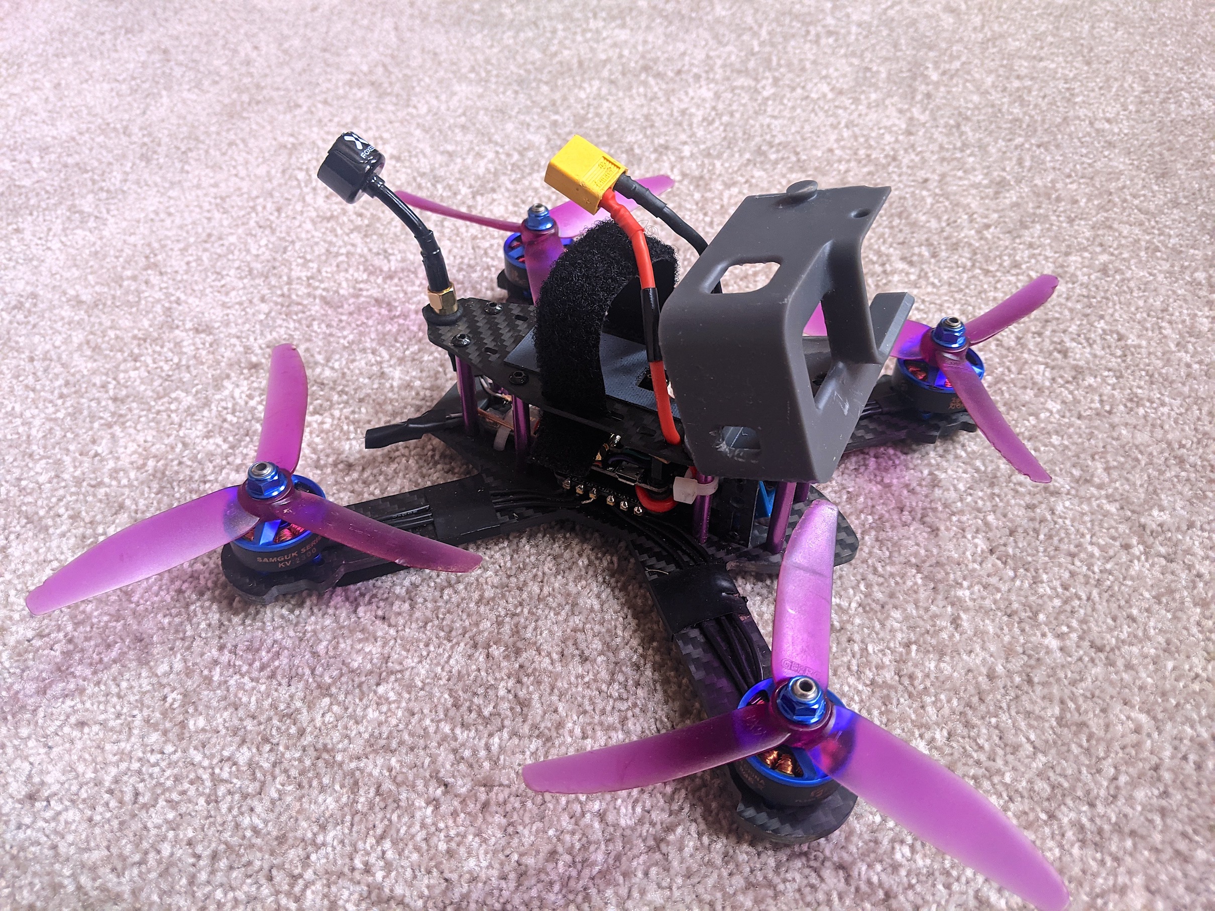
the crude Arduino based algorithms where they started. You can see my first racing drone to the right. It
runs on an M4 processor clocked at 140 MHz. It weighs just over one kilogram, the motors max out at
about 30,000 RPM, and it draws almost three horsepower at full throttle, giving it a thrust to
weight ratio five times that of an F-18.
Of course, much of the enjoyment of aircraft and RC vehicles comes from building them myself.
Combining this interest with my interest in photography gave me the idea to engineer, design, and
build a fully autonomous vehicle for capturing ultra smooth video and photos.
This new drone would not need to be ultra high performance, but it would need to fly for longer
between charges, and be able to carry a 3 axis gimbal and higher quality camera. Additionally, I
wanted to properly engineer all aspects of this drone, rather than simply buying and assembling
parts off the internet. There is very little actual engineering data available for off the shelf
parts within the RC community. Rather, pairing motors, batteries, and propellers is almost entirely
anecdotal. Occasionally manufacturers will recommend a specific propeller-motor combination. This
means that I needed to empirically measure and quantify the characteristics of many different motors
and propellers myself. This in-turn led to the development of my Motor and Propeller Dynamometer &
Test Stand. A photo of that device can be seen below.
And a full description of its operation can be
read here.
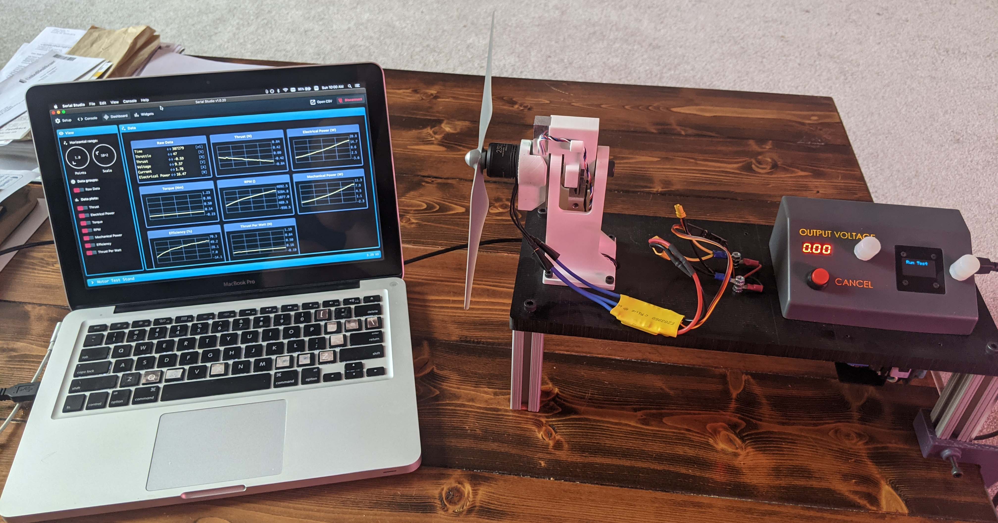 This device measures electrical input power, mechanical output power, thrust, RPM, and a number of
other metrics. Using these measurements. I have been able to fully characterize the torque curves
and efficiency curves of both motor and propeller combinations, at different voltage and power
levels. Using this data I can optimize the power system for high thrust to power ratios, and low
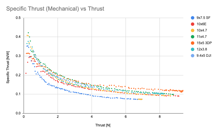
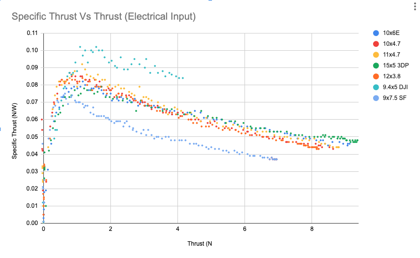
weight. Below you can see an example graph of a specific thrust for some of the propellers I tested.
This is a measure of static thrust produced per unit of mechanical input power. You can see that (as
expected from theory) running larger propellers more slowly is generally more efficient (at the
expense of size and weight).
This device measures electrical input power, mechanical output power, thrust, RPM, and a number of
other metrics. Using these measurements. I have been able to fully characterize the torque curves
and efficiency curves of both motor and propeller combinations, at different voltage and power
levels. Using this data I can optimize the power system for high thrust to power ratios, and low
weight. Below you can see an example graph of a specific thrust for some of the propellers I tested.
This is a measure of static thrust produced per unit of mechanical input power. You can see that (as
expected from theory) running larger propellers more slowly is generally more efficient (at the
expense of size and weight).
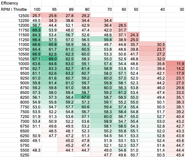 Above is a heatmap of one of the motors I tested. This is a 3D plot of the efficiency of the motor
vs RPM and throttle. The green areas are higher efficiency, and red is lower. During the testing of
these common motors and propellers, I discovered a disturbing trend among all of the commonly
available parts for RC vehicles. That is that generally, motors are over-propped by most
recommendations. That is, they are running a propeller at too low an RPM, that provides too little
resistance. By running a smaller propeller faster, they could achieve the same thrust, but
consume 5-10% less energy. The one exception to this that I found was a motor propeller combination
from a DJI Phantom 4 Drone. They use both a custom motor size as well as a custom propeller size,
neither of which are available elsewhere. This custom combination gives a 15-20% thrust-to-power
increase over the other parts I tested. Clearly DJI engineers are doing things right. I even
designed a 15 inch propeller using Solidworks fluid simulation, and printed it on a high resolution
SLA 3D printer. But I was only barely able to match the performance of the other cheap Chinese propellers.
A comparison of all tested propellers can be seen below.
Above is a heatmap of one of the motors I tested. This is a 3D plot of the efficiency of the motor
vs RPM and throttle. The green areas are higher efficiency, and red is lower. During the testing of
these common motors and propellers, I discovered a disturbing trend among all of the commonly
available parts for RC vehicles. That is that generally, motors are over-propped by most
recommendations. That is, they are running a propeller at too low an RPM, that provides too little
resistance. By running a smaller propeller faster, they could achieve the same thrust, but
consume 5-10% less energy. The one exception to this that I found was a motor propeller combination
from a DJI Phantom 4 Drone. They use both a custom motor size as well as a custom propeller size,
neither of which are available elsewhere. This custom combination gives a 15-20% thrust-to-power
increase over the other parts I tested. Clearly DJI engineers are doing things right. I even
designed a 15 inch propeller using Solidworks fluid simulation, and printed it on a high resolution
SLA 3D printer. But I was only barely able to match the performance of the other cheap Chinese propellers.
A comparison of all tested propellers can be seen below.
 (photo of 3D printed propeller)
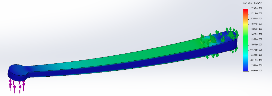
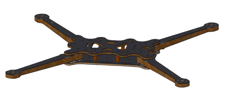
The frame was the next consideration to make. Critically, it should be light and stiff. Typically
this just depends on how much money you are willing to throw at the problem. After some more
Solidworks stress and resonance simulations, I settled on a composite design of thin carbon fiber
sheets laminated to balsa wood. Carbon fiber is, of course, extremely strong and stiff. But a solid
carbon body would be much too heavy, and much stronger than needed. Balsa wood is one of the highest
stiffness-to-weight materials available to makers such as myself, but it is not very strong. By
laminating carbon and wood, the final body is about 200 times stiffer than the same weight of carbon
alone, but only weighs three times as much. This is because the outer carbon takes about 92% of the
load. Because the wood is not very strong. Both materials are used optimally to their max strength.
But because the wood is extremely light, the sum total is also very light.
(photo of 3D printed propeller)
The frame was the next consideration to make. Critically, it should be light and stiff. Typically
this just depends on how much money you are willing to throw at the problem. After some more
Solidworks stress and resonance simulations, I settled on a composite design of thin carbon fiber
sheets laminated to balsa wood. Carbon fiber is, of course, extremely strong and stiff. But a solid
carbon body would be much too heavy, and much stronger than needed. Balsa wood is one of the highest
stiffness-to-weight materials available to makers such as myself, but it is not very strong. By
laminating carbon and wood, the final body is about 200 times stiffer than the same weight of carbon
alone, but only weighs three times as much. This is because the outer carbon takes about 92% of the
load. Because the wood is not very strong. Both materials are used optimally to their max strength.
But because the wood is extremely light, the sum total is also very light.
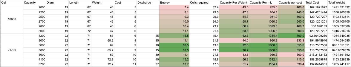
 The body also needs to be large enough to carry all of the batteries and other electronics required.
The good news is that most of these parts are static. They do not change their size or weight
depending on other factors. The only item that does this is the batteries. To determine the optimal
size for the frame, I compiled all of the known part weights into a spreadsheet. I also calculated
the size and weight of a theoretical battery pack. A bigger battery contains more energy, of course,
but weighs more which requires a larger frame and requires more power to lift. I was able to use the
Solidworks iterative design study to output the weight of the frame required to carry different
energy capacities of batteries. Adding these equations to the spreadsheet with the thrust curves above
allowed me to calculate the thrust
required, power required, and then the expected flight time for any chosen battery size.
The body also needs to be large enough to carry all of the batteries and other electronics required.
The good news is that most of these parts are static. They do not change their size or weight
depending on other factors. The only item that does this is the batteries. To determine the optimal
size for the frame, I compiled all of the known part weights into a spreadsheet. I also calculated
the size and weight of a theoretical battery pack. A bigger battery contains more energy, of course,
but weighs more which requires a larger frame and requires more power to lift. I was able to use the
Solidworks iterative design study to output the weight of the frame required to carry different
energy capacities of batteries. Adding these equations to the spreadsheet with the thrust curves above
allowed me to calculate the thrust
required, power required, and then the expected flight time for any chosen battery size.
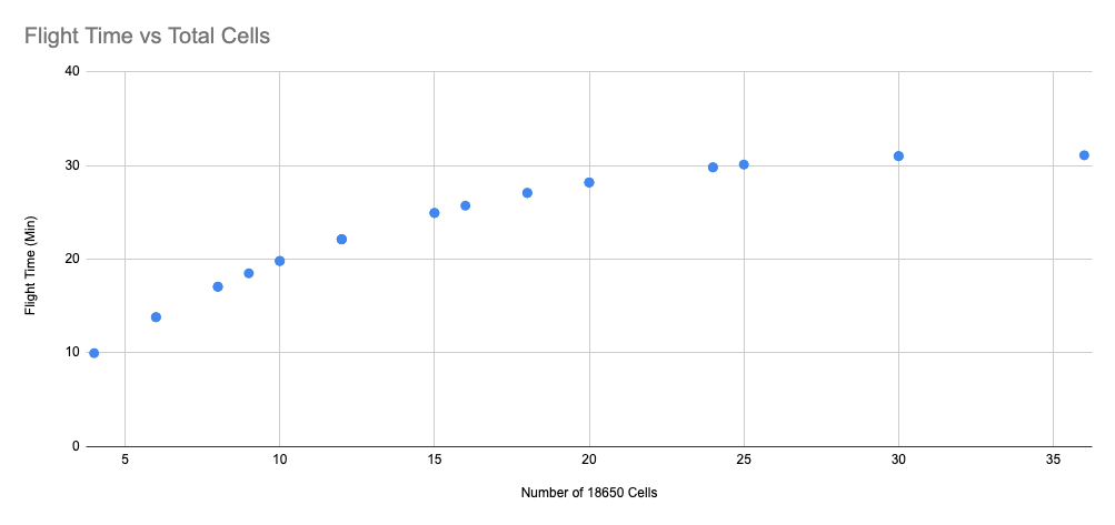
 By plotting these values I found that the optimal flight time of 25-30 minutes could be achieved with a
battery of anywhere from 100 to 200 Watt-Hours (flight time gain diminishes above ~30 min. More
battery seems to only add enough energy to lift its own additional weight, but does not allow for
any longer flights). I settled on a frame design that was light, but had a bit of extra room if I ever
did want to put a larger battery onboard. Running the battery calculation showed a max flight time of just over 30 minutes.
You can see this graph below. Below that you can see some photos of the CAD of the mostly completed design.
By plotting these values I found that the optimal flight time of 25-30 minutes could be achieved with a
battery of anywhere from 100 to 200 Watt-Hours (flight time gain diminishes above ~30 min. More
battery seems to only add enough energy to lift its own additional weight, but does not allow for
any longer flights). I settled on a frame design that was light, but had a bit of extra room if I ever
did want to put a larger battery onboard. Running the battery calculation showed a max flight time of just over 30 minutes.
You can see this graph below. Below that you can see some photos of the CAD of the mostly completed design.
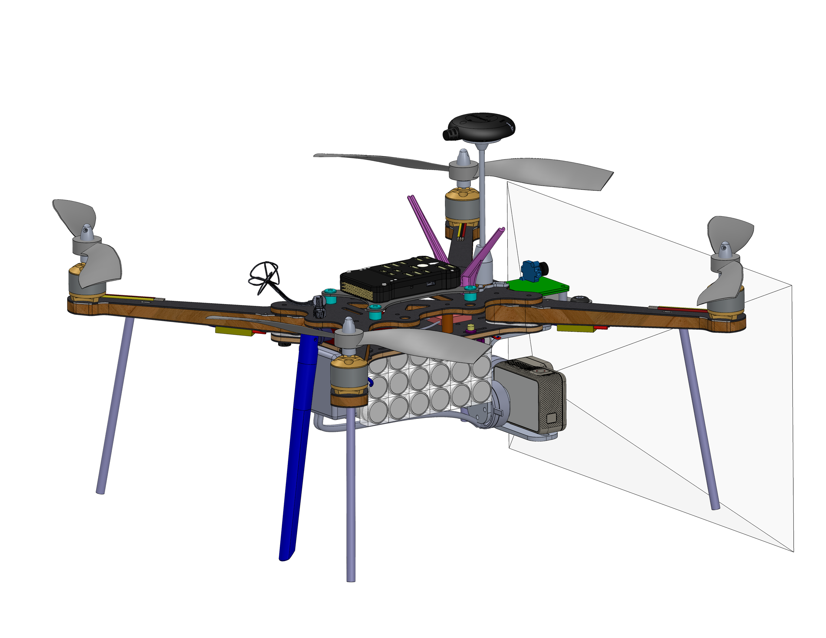
 There is room for a flight controller, GPS, telemetry radio, video radio, RC control radio, motor
drivers, and a massive battery pack made from 19650 lithium ion cells. Additionally, you can see
that I added in a GoPro camera and a 3 axis gimbal (also included in the flight time calculations).
This camera can be used to record high quality video from the air. The 3 Axis gimbal adds the
possibility of pointing at a subject that contradicts the flight direction of the aircraft. But it
also can be used to mechanically stabilize the rotations and turns of the aircraft for buttery
smooth video.
There is room for a flight controller, GPS, telemetry radio, video radio, RC control radio, motor
drivers, and a massive battery pack made from 19650 lithium ion cells. Additionally, you can see
that I added in a GoPro camera and a 3 axis gimbal (also included in the flight time calculations).
This camera can be used to record high quality video from the air. The 3 Axis gimbal adds the
possibility of pointing at a subject that contradicts the flight direction of the aircraft. But it
also can be used to mechanically stabilize the rotations and turns of the aircraft for buttery
smooth video.
I am still waiting on a number of electrical components from China to complete this drone.
Unfortunately, the covid pandemic chip shortage seems to even be affecting hobby drone flying. In
the mean-time, there is certainly mechanical construction and a lot of firmware to be written.