This project was inspired by the “QlockTwo” by Biegert and Funk. If you’ve seen their website, you
know how ridiculously expensive their clock is. I set out to build my own, but not before making
some improvements, of course!
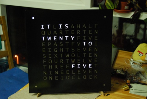
Below is a video of the finished clock. The rest of this page shows the details of the building process.
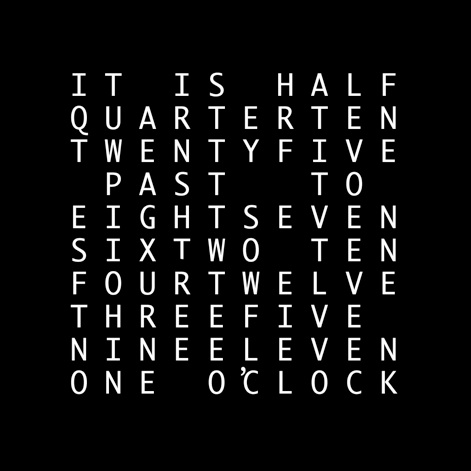
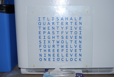
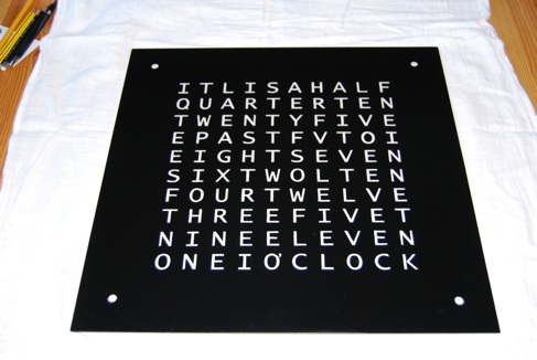
Above is the array of letters I arrived at for my clock. As you can see, just as with the QlockTwo, the time
can be read to the nearest five minutes. However this one uses only a 10-by-10 array of letters, as opposed
to the QlockTwo’s 11-by-10. This makes the array square, and it uses a nice even 100 LEDs.
The first thing I did was cut out the glass from a much larger picture frame, into a 16-by-16-inch square
for the lettered front. This left a few extra pieces of glass, which I used as “practice pieces.” I didn’t
want the practice pieces to go to waste, so I used one of the smaller ones to make a binary clock.
Although the glass front measures 16^2 inches, the 10-by-10 array of letters only takes up 11^2 inches.
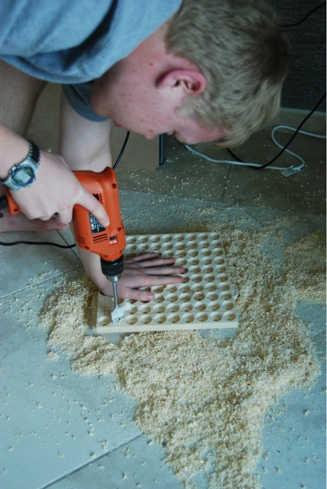
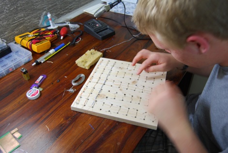
Here I’m using a one-inch bit to make 5/8th-inch deep holes in a 3/4-inch thick board. The tip of the
bit left a perfect 5mm hole in which to fit each LED.
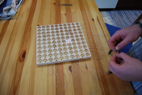
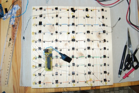
I extracted 100 LEDs out of one of many bargain-bin strings of Christmas lights I bought. Here I’m
multiplexing them into 10 columns and 5 rows.
Done multiplexing, I’m using a coin cell battery to test each LED. I just need to find the right value
resistor...
And..... it works!! Well one of them does...
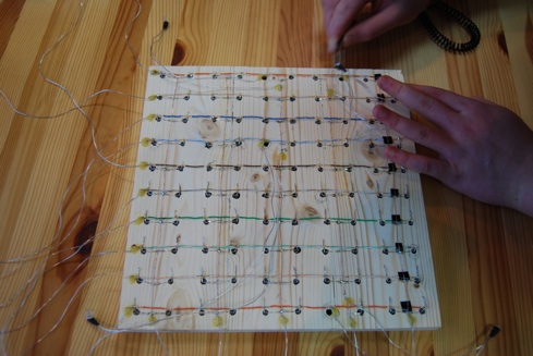
And here’s a view of the backside. The wires to four of the LEDs have been extended; they will sit
behind the glass a few inches off the corners of the wood. They indicate single minutes, improving
upon the five-minute accuracy of the words.
The LEDs are controlled by my favorite microcontroller development board --- the Arduino UNO.
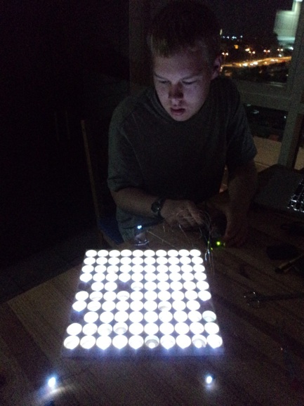
Here I’m running a simple brightness test. Due to the power restriction of the Arduino and the
nature of multiplexing, no more than five LEDs can be driven at one time. The LEDs in this picture
are each running at about 100 Hz with a 5% duty cycle. Plenty bright at night, but could be better
during the day.
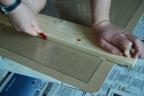
Below you can see the beginning of the next step. I’m using painter’s tape as stencils that I can
peel off the glass after painting. The painter’s tape
works well because it doesn’t leave any residue.
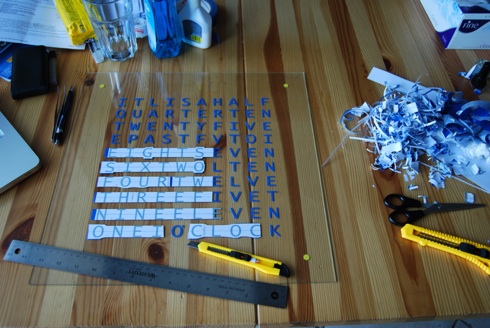 Below, is the glass with the finished tape stencils.
 And here the glass has been painted; I used a satin-finish indoor-outdoor black spray paint. I’ve already
begun to peel off some of the letters.
And here the glass has been painted; I used a satin-finish indoor-outdoor black spray paint. I’ve already
begun to peel off some of the letters.
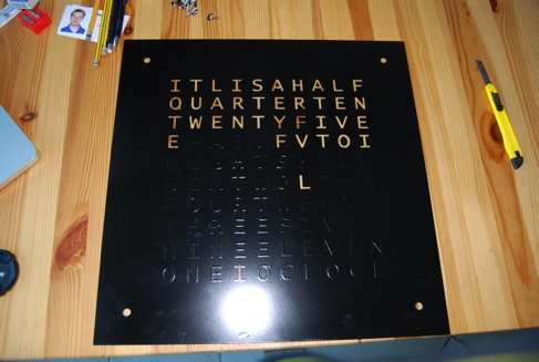 Here all of the stencils have been peeled off...
The letters are completely clear, so I used a glass etching cream to give them a frosted look.
This will also help diffuse the light from the LEDs making the letters less directional.
Here all of the stencils have been peeled off...
The letters are completely clear, so I used a glass etching cream to give them a frosted look.
This will also help diffuse the light from the LEDs making the letters less directional.
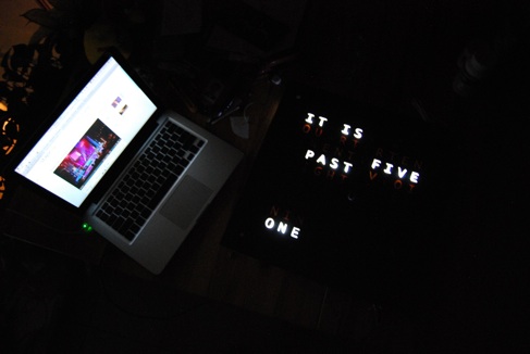
 ...and here I’m using an Arduino UNO board to light the LEDs while I write and fine tune the
software. (as you can see from the computer screen I was also doing a bit of procrastination)
...and here I’m using an Arduino UNO board to light the LEDs while I write and fine tune the
software. (as you can see from the computer screen I was also doing a bit of procrastination)
 Once the software was working I soldered up a small board with a stand-alone chip. The chip is the same
one as in Arduinos (‘Arduini’? -- ATmel’s ATmega328p), except without all of the unnecessary components
such as a crystal, serial to USB converter, and 3.3V power supply.
Once the software was working I soldered up a small board with a stand-alone chip. The chip is the same
one as in Arduinos (‘Arduini’? -- ATmel’s ATmega328p), except without all of the unnecessary components
such as a crystal, serial to USB converter, and 3.3V power supply.
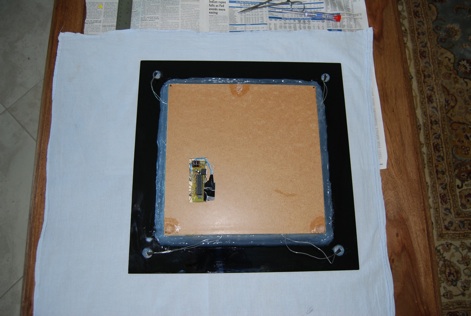
 Here’s a more finalized clock, with a protective backing.
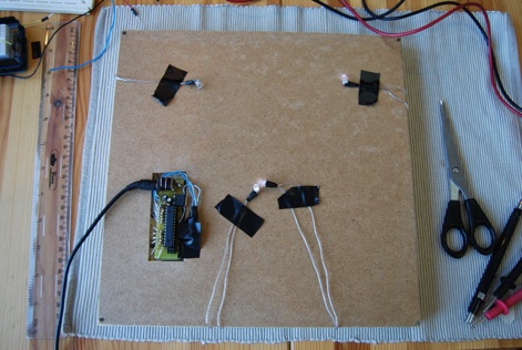 The wooden square and all of the LEDs are held to the glass by silicone caulk. The silicon bonds extremely
well to the glass, but not at all to the wood. This allows me to remove the LEDs and electronics if need be.
The wooden square and all of the LEDs are held to the glass by silicone caulk. The silicon bonds extremely
well to the glass, but not at all to the wood. This allows me to remove the LEDs and electronics if need be.
 And finally, here is a shot of the finished project in action.