This project is a little bit different. This was my senior project. I worked on this project for
a full semester along with five other students.
The premise of the project was to build a stirling engine designed to be used as a heat pump in
place of traditional refrigeration devices.
For those people not familiar with stirling engines, they are a device which can convert a
temperature differential into a mechanical energy. The cool thing about stirling engines,
however, is that they can also be run in reverse, that is, by applying mechanical power, they
produce a temperature difference that can be used to pump heat. Their theoretical efficiency is
extremely high. Significantly higher than traditional types of refrigerators. This is the
underlying concept that we wanted to pursue.
The first step was to find a suitable refrigerator to retrofit. We managed to get hold of a
standard mini fridge. The type one might see in a college dorm room.
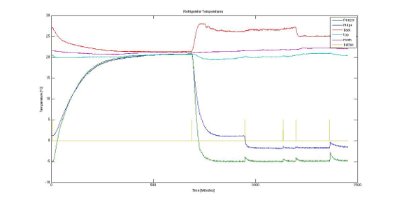
We needed to be able to quantify a number of parameters such as efficiency, maximum rate of
cooling, etc. We first tried to take measurements by plugging the refrigerator in and allowing
it to cool while measuring the energy consumption and temperature inside and outside. A graph of
the temperatures recorded can be seen below. The rate of temperature change at the beginning of
the graph should theoretically allow us to calculate the combined thermal resistivity of the
refrigerators walls, from which we can calculate a theoretical energy requirement for
maintaining a specified temperature. Unfortunately, inaccuracies in the temperature, voltage,
current, and refrigerator dimensions meant that our margin of error was much too wide.
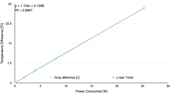
 In order to get a more accurate specification, we employed a different technique. This involved
placing a nichrome wire wound resistor inside of the refrigerator and applying various voltages
to it. The theory behind this approach is as follows: Resistive heating can be assumed to be
close to 100% efficient. By accurately measuring the voltage and current being applied to the
resistor we can know very accurately how much thermal energy the resistor is dissipating. By
allowing the temperature inside the fridge to rise to steady state, and reading the temperature
we will know the degree temperature change per Watt of the fridge. To achieve an even more
accurate measurement the test can be repeated at various levels of power dissipation. Below a
graph can be seen of the results of these tests as well as a linear best fit line. The slope of
this line indicates the combined thermal resistance of the refrigerator. In this case our
results was 1.119 degrees per Watt. This means that if we wanted to achieve a 30 degree
temperature differential, thermal energy would have to be removed from the refrigerator at a
rate of 30/1.119 = 36.8 Watts.
In order to get a more accurate specification, we employed a different technique. This involved
placing a nichrome wire wound resistor inside of the refrigerator and applying various voltages
to it. The theory behind this approach is as follows: Resistive heating can be assumed to be
close to 100% efficient. By accurately measuring the voltage and current being applied to the
resistor we can know very accurately how much thermal energy the resistor is dissipating. By
allowing the temperature inside the fridge to rise to steady state, and reading the temperature
we will know the degree temperature change per Watt of the fridge. To achieve an even more
accurate measurement the test can be repeated at various levels of power dissipation. Below a
graph can be seen of the results of these tests as well as a linear best fit line. The slope of
this line indicates the combined thermal resistance of the refrigerator. In this case our
results was 1.119 degrees per Watt. This means that if we wanted to achieve a 30 degree
temperature differential, thermal energy would have to be removed from the refrigerator at a
rate of 30/1.119 = 36.8 Watts.
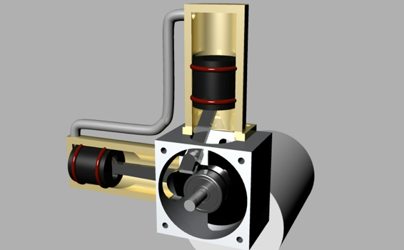
 The next step was, of course, to design the stirling engine itself. We started by designing a
shape that we though would fit well inside of the mini fridge we had acquired. A rendering of
the final CAD model can be seen below. This is a common alpha style stirling engine. Because the
two pistons are 90 degrees out of phase, the working fluid (in our case air) is compressed in
one cylinder, and rarefied in the other cylinder. This causes one cylinder to become colder and
absorb heat, while the other becomes warm and loses heat. Of course there has to be mechanical
energy added for the thermal energy done. This comes from the electric motor at the back of the
crank case.
The next step was, of course, to design the stirling engine itself. We started by designing a
shape that we though would fit well inside of the mini fridge we had acquired. A rendering of
the final CAD model can be seen below. This is a common alpha style stirling engine. Because the
two pistons are 90 degrees out of phase, the working fluid (in our case air) is compressed in
one cylinder, and rarefied in the other cylinder. This causes one cylinder to become colder and
absorb heat, while the other becomes warm and loses heat. Of course there has to be mechanical
energy added for the thermal energy done. This comes from the electric motor at the back of the
crank case.
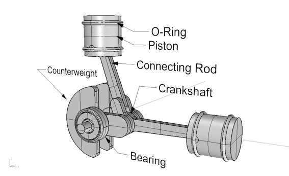
 A clearer image of the piston and crankshaft assembly can be seen below.
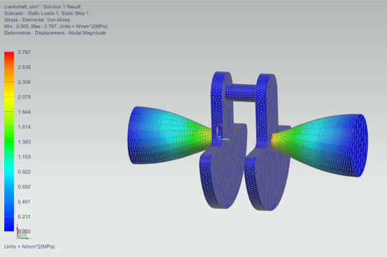
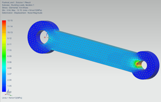
 After the first design of the engine through thermal calculations we wanted to verify our design
through simulation as well. For this we used Siemens’ NX. NX is a powerful tool for finite
element analysis, that can do fluid, thermal, stress, strain, impact and impulse simulations as
well as cyclical fatigue simulations. Each of the critical parts of the engine was tested for
thermal and structural properties. Below you can see torsional and compression stress
simulations on the crankshaft and connecting rod, respectively.
After the first design of the engine through thermal calculations we wanted to verify our design
through simulation as well. For this we used Siemens’ NX. NX is a powerful tool for finite
element analysis, that can do fluid, thermal, stress, strain, impact and impulse simulations as
well as cyclical fatigue simulations. Each of the critical parts of the engine was tested for
thermal and structural properties. Below you can see torsional and compression stress
simulations on the crankshaft and connecting rod, respectively.
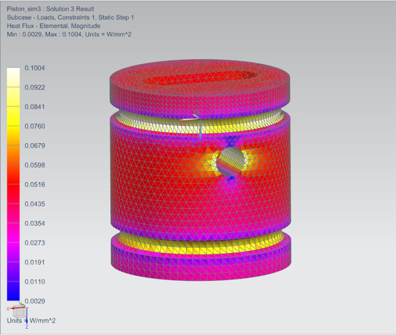
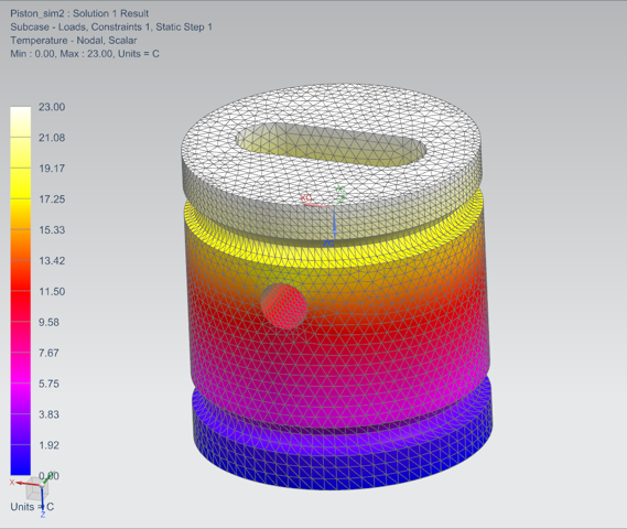
 Below you can see two simulations that were run on the piston: Thermal flux and temperature.
These are just two of the many simulations run.
It should be noted that the heat flux increases in areas of the piston with small(er) cross
sectional area. This is exactly what we would expect from our hand calculations.
Below you can see two simulations that were run on the piston: Thermal flux and temperature.
These are just two of the many simulations run.
It should be noted that the heat flux increases in areas of the piston with small(er) cross
sectional area. This is exactly what we would expect from our hand calculations.
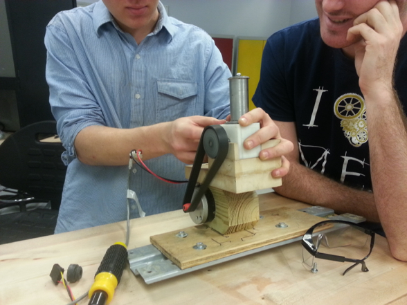
 We used a combination of machining and 3D printing to make the final stirling engine. Below you
can see the engine running while we tested. Unfortunately the rubber O-rings that we used
created much too much friction which in turn generated significant heat. This is a problem that
we were never able to fully solve. We talked to a number of professional machinist as well as
people with hydraulic and seals experience, but all were stumped. In the end, we managed to
reduce the friction enough to achieve a few degrees temperature drop below atmospheric, but not
enough to compete with commercial refrigerators.
We used a combination of machining and 3D printing to make the final stirling engine. Below you
can see the engine running while we tested. Unfortunately the rubber O-rings that we used
created much too much friction which in turn generated significant heat. This is a problem that
we were never able to fully solve. We talked to a number of professional machinist as well as
people with hydraulic and seals experience, but all were stumped. In the end, we managed to
reduce the friction enough to achieve a few degrees temperature drop below atmospheric, but not
enough to compete with commercial refrigerators.
 For those people that are super interested, an early
version of our class’ final report is available here.
For those people that are super interested, an early
version of our class’ final report is available here.