Many commercial products benefit from the massive advancements in technology that happens over time. Us makers
can only make crude simplified versions of what can be made commercially due to the manufacturing technology
involved. However this is one of the few projects where a person with simple tools can relatively easily make a
device not just as good, but substantially better than is commercially available (at least for the same cost).
All that is required is some time, and a bit of care.
A ribbon microphone is a type of microphone that has fallen out of popularity (other than in very high end
recording) due to their high cost and delicate nature. However they used to be considered the gold standard for
audie reproduction quality. A traditional microphone uses a circular diaphragm attached to a coil of wire in a
magnetic field. When sound interacts with the diaphragm, it vibrates, inducing a voltage in the coil. This
voltage is typically a few mv or less at very high impedance. A ribbon microphone uses a strip of ultra thin conductive
foil (usually aluminum) in a magnetic field instead of a diaphragm. And instead of vibrating a coil of wire, the
strip of metal acts as a single conductive wire in the magnetic field.
Because the strip of foil has a much
lower resistance and only a single “turn” compared to the coil.
The output signal is orders of magnitude lower,
usually a few tens of microvolts. However, it is also a very low impedance signal. This makes the signal much
less susceptible to RF noise and static charge. Additionally, because the surface area of the foil is so large,
and it’s mass is so small, its acoustic impedance is very low. This means that the physical vibrations (and thus
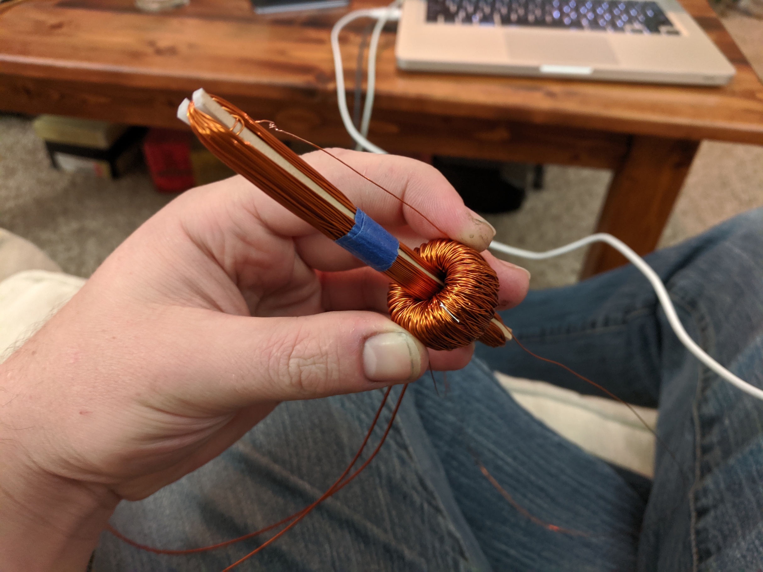
electrical signal) very very accurately represent the original sound waves. Because the signal voltage is so
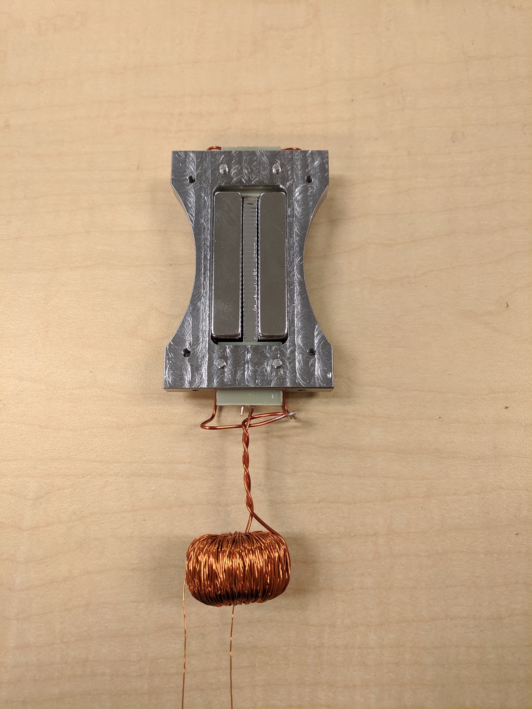
low, an impedance matching transformer is typically used. I found a ferrite toroid in my bin of parts, and wound
a few hundred turns of 22 gauge enameled wire, making a 35:1 transformer. Toroidal transformers are considered
the gold standard in terms of noise rejection and efficiency due to their smooth symmetric shape. Because they
are hard to wind, they are also extremely expensive.
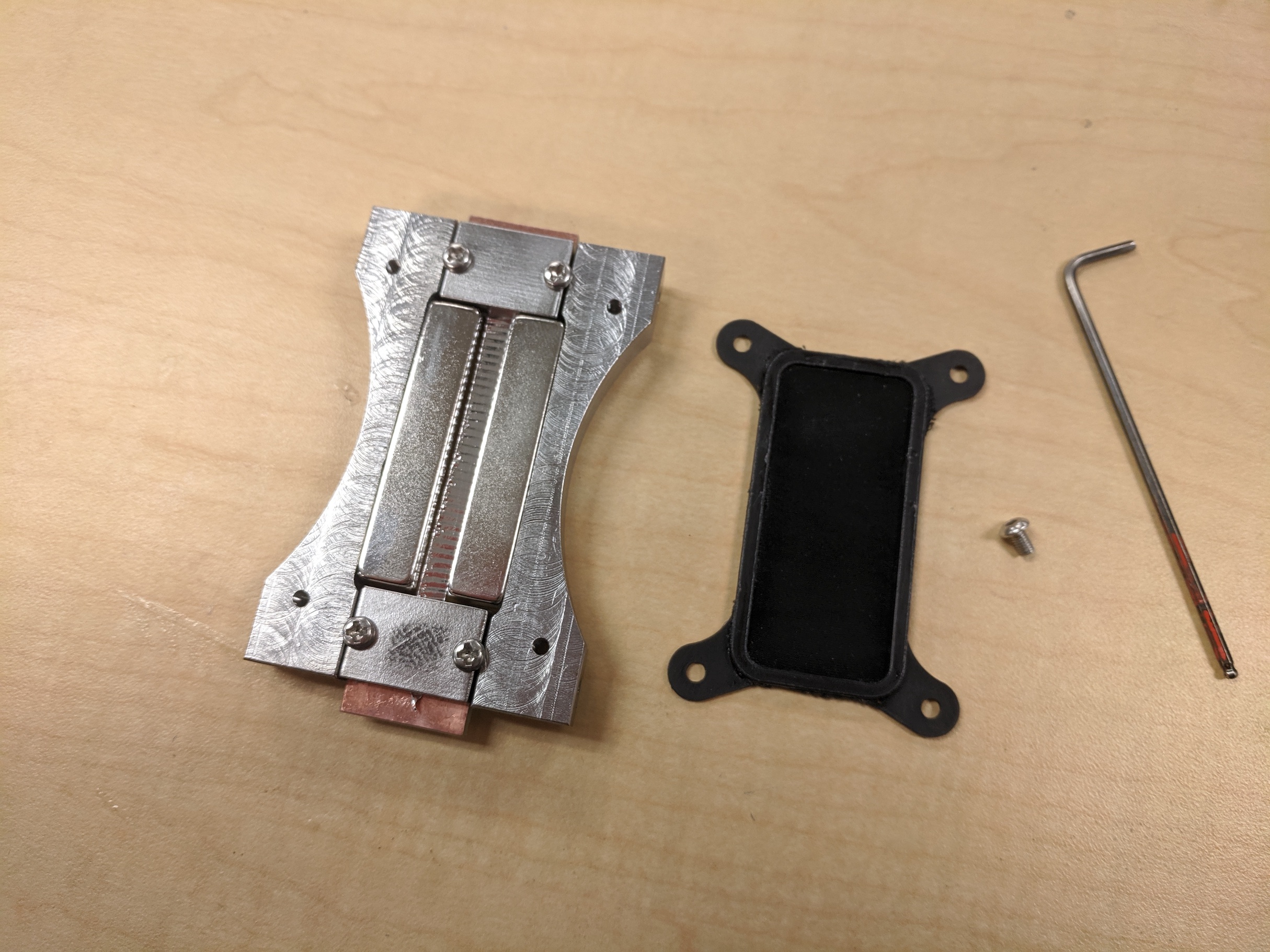
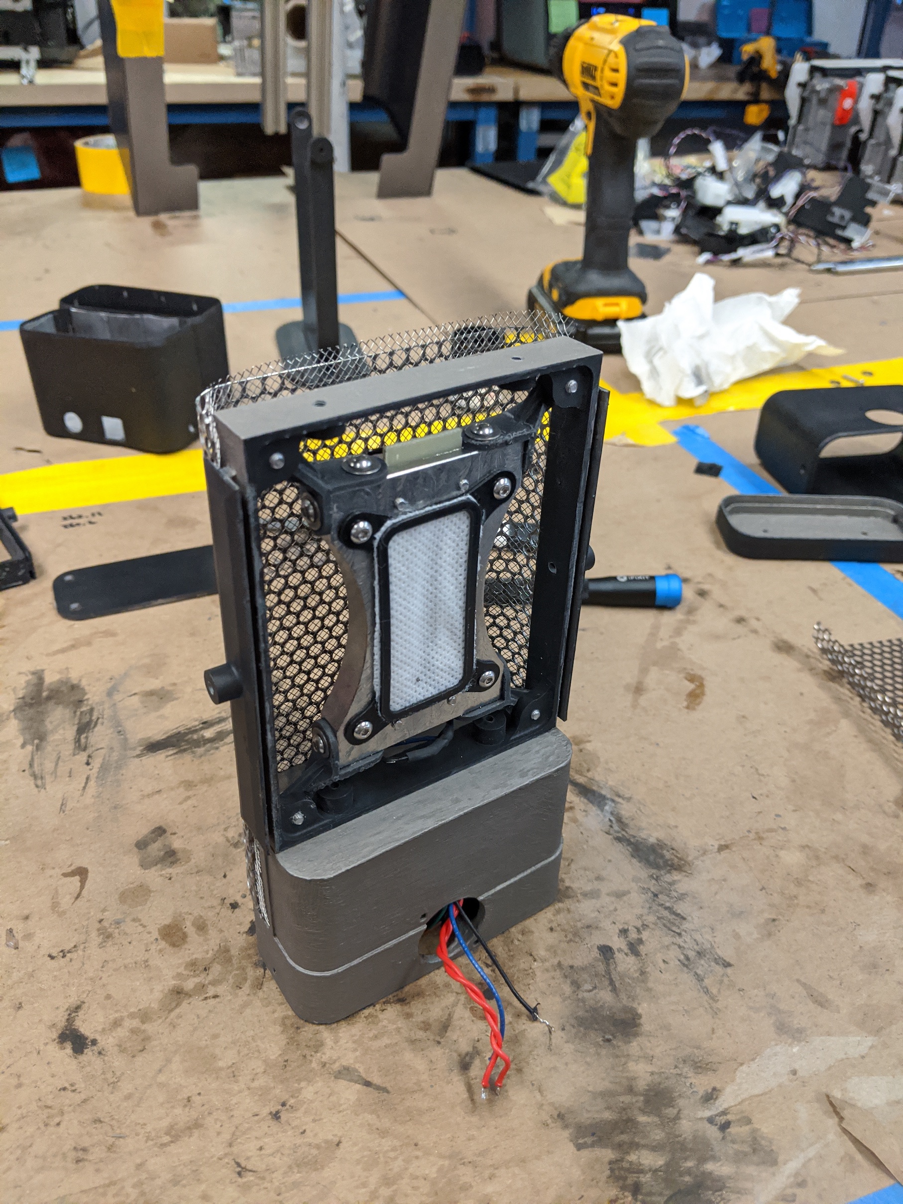
Below you can see the internal frame of the microphone. It is machined from a high magnetic permeability steel. On
either side of the ribbon strong N52 magnets are glued in place. These create a strong magnetic field over the
width of the ribbon. The frame helps contain the magnetic flux, so magnetic dust does not want to stick to the
mic, and so nearby magnetism sensitive devices are not affected. The ribbon is made from 10 micron thick aluminum. It is delicately
clamped on both ends to a piece
of fiberglass PCB. These serve as electrical connections that can be soldered.
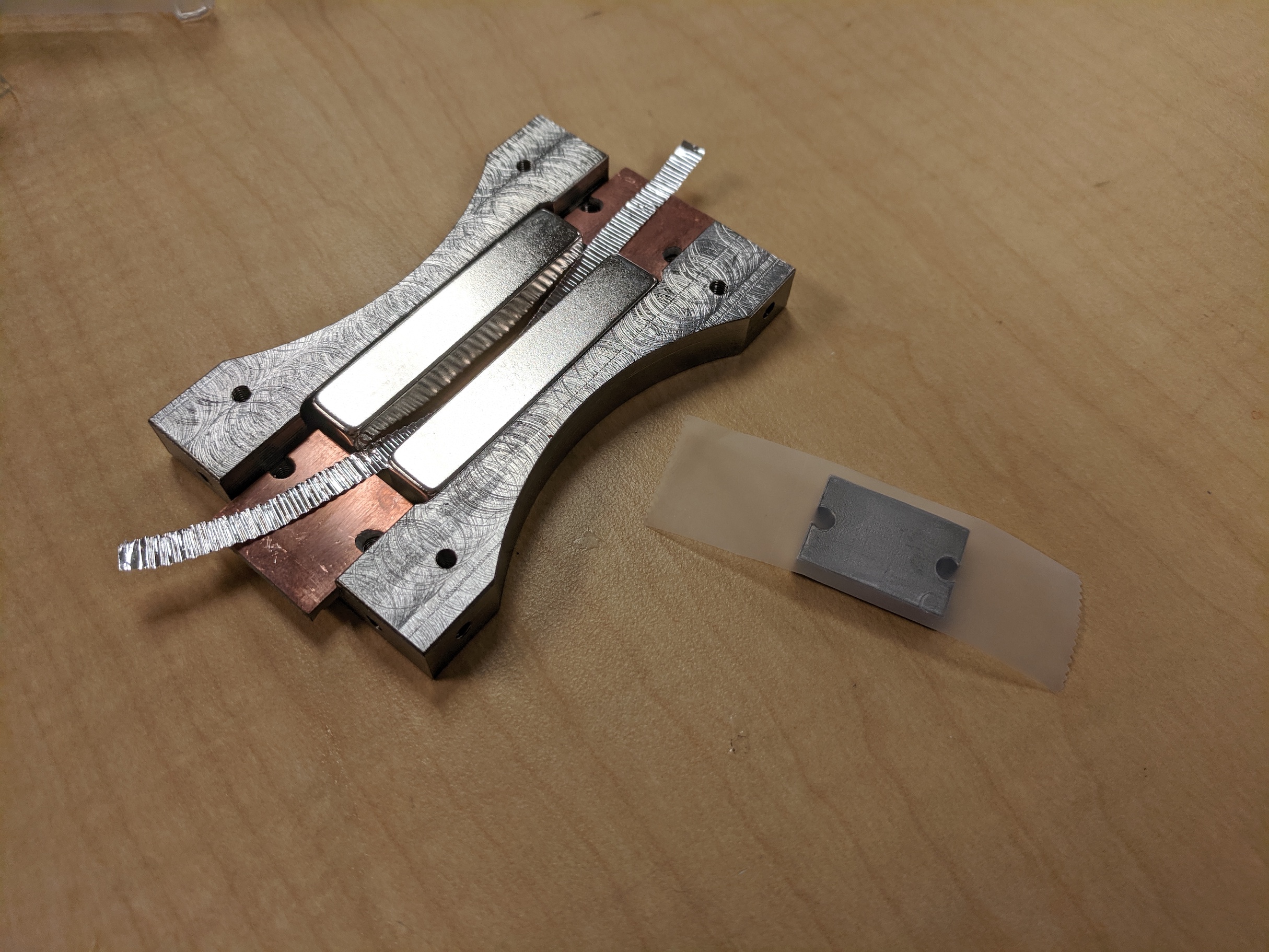
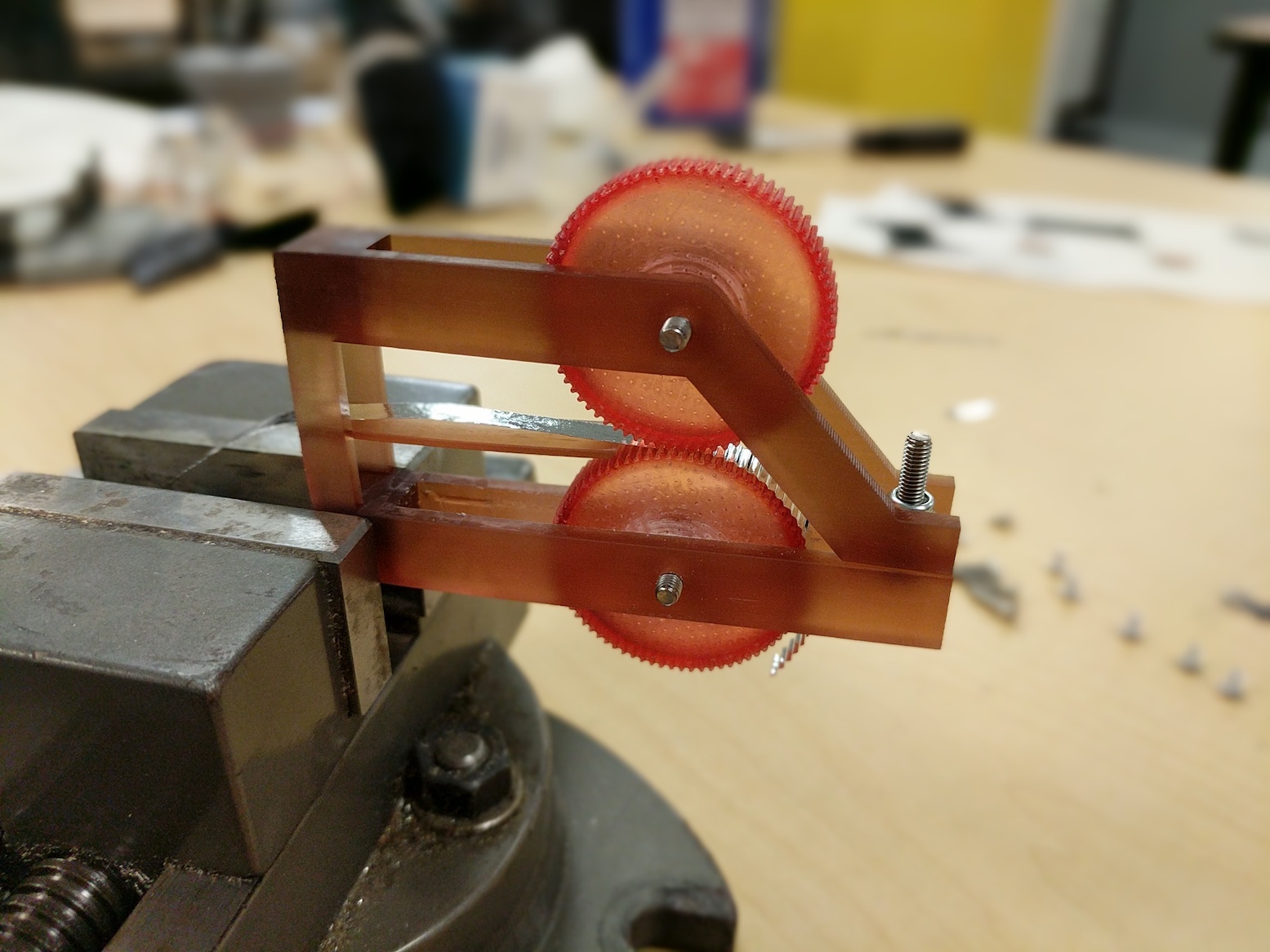
The ribbon is corrugated to change its effective stiffness. I did this by sandwitching it in tissue paper, and
then rolling it between two 3D printed gears. This has a large impact on the sound quality of the
final microphone. Because the ribbon acts as a spring, and it has mass, it has a resonant frequency. The
corrugations also allow the tension in the ribbon to be tuned to achieve the desired resonant frequency. I did
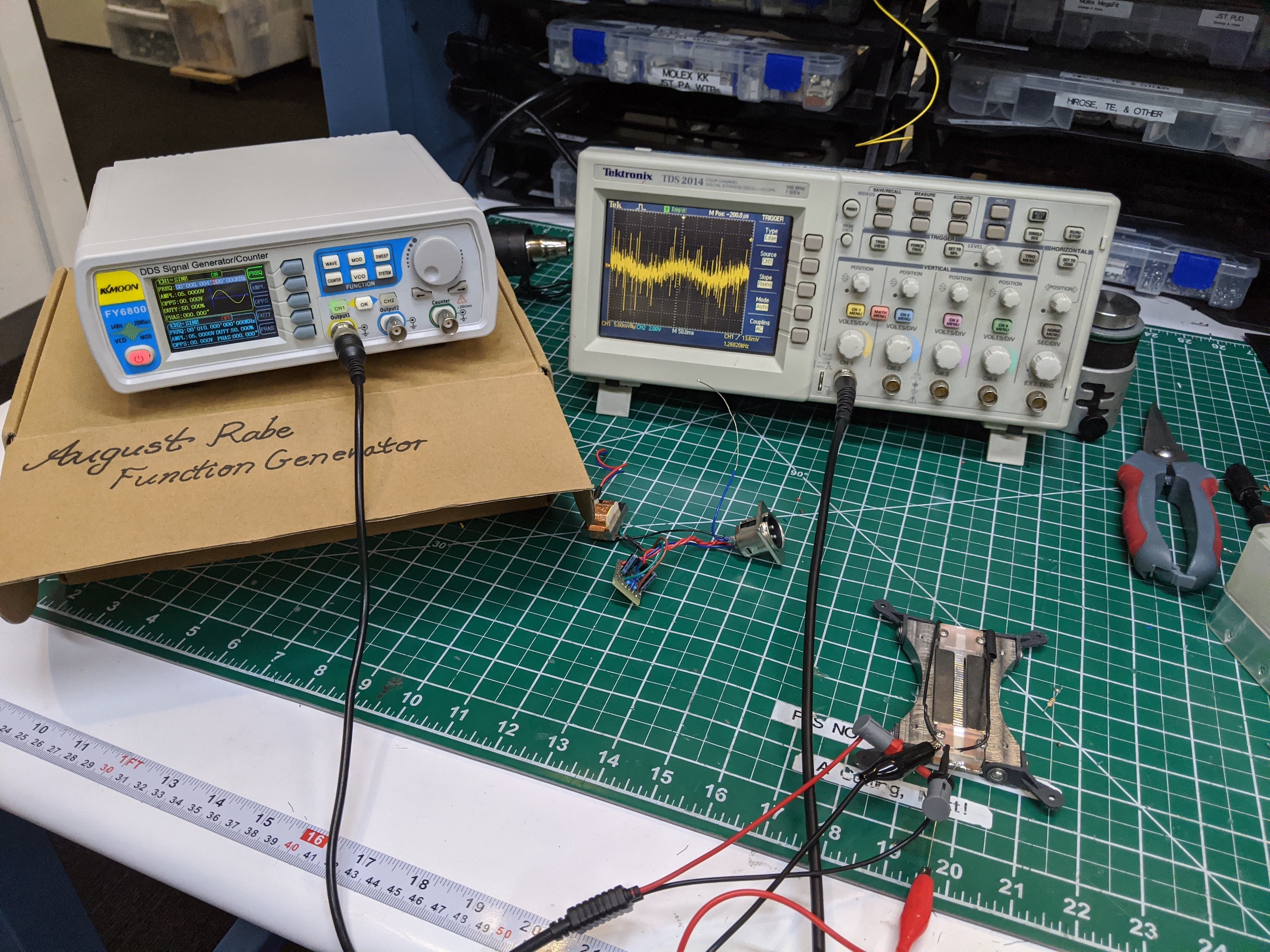
this by reflecting a laser off the ribbon onto the wall. I fed a low voltage sine wave into the ribbon with a
function generator. This caused the ribbon to vibrate, creating a line on the wall from the laser. By adjusting
the signal frequency, I could find the point at which the laser, and ribbon deflection was the maximum. This is
the resonant frequency. I tuned it to about 60 Hz. This turned out to be a bit too low, as this microphone
already exhibits a strong proximity effect, creating somewhat boomy audio from nearby sources.
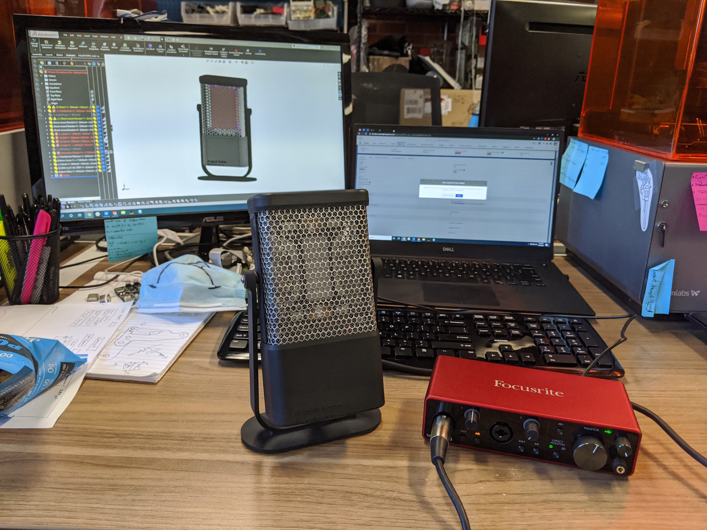
This inner frame needed a housing so, in Solidworks, I designed a 3D printed enclosure. Using highly damped but
very flexible printed parts I was able to shock mount the core within an outer frame for additional noise reduction.
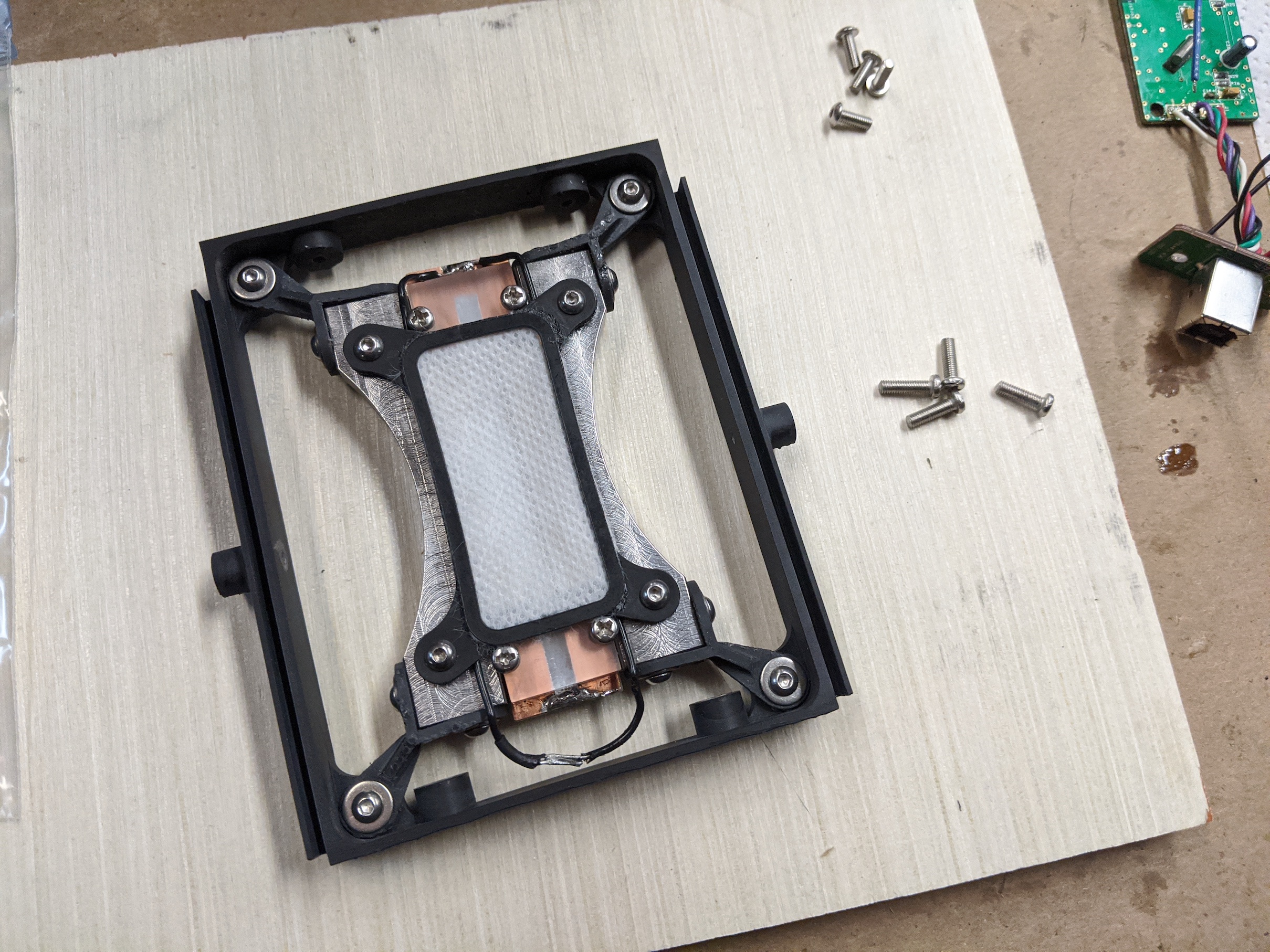
The enclosure also contains a
custom preamplifier circuit powered by standard 48V phantom power. I tested many different ultra low noise
amplifiers, and eventually settled on a very simple two transistor, class-A design made from discrete components. This ended
up being much lower noise than any cheap amplifier that I could buy. It may reduce the linearity slightly, but the simulations indicated
less than 0.1% total harmonic distortion over the full opperating range. I think that's a reasonable tradeoff. I used LT Spice to simulate the circuit for
gain, linearity, stability, and to choose the component values.

This circuit was shielded, and placed inside the microphone housing. Additionally, the entire inside of the
housing was painted in a nickel based conductive paint for further shielding. The open areas of the mic were
enclosed in a fine steel mesh.
Initial testing of the microphone made me realize just how garbage the quality
is of cheap audio inputs on phones and computers. So I purchased an
entry level USB audio interface with good reviews and good specs. Although the audio input noise floor is very
low, the microphone noise floor is still completely undetectable. I certainly don’t have access to equipment
good enough to measure it. But it is certainly below the limit of human hearing.
But what about the recording quality? Well, I don’t have experience with high quality microphones, so this may
not mean much, but my homemade microphone is definitely the highest quality, best sounding microphone I have
ever used. I do, however, need to learn how to properly record audio. You can watch me struggle to sing in the youtube video below.