One of my hobbies outside of engineering projects is photography. A particularly interesting
photography technique is time-lapse. In time-lapse photography, a video is produced by taking
hundreds of still images at regular intervals (usually a few seconds) over the course of hours or
even days. The photos are then compiled into a video. When played back at a standard 24 or 30 frames
per second. The video shows the subject greatly sped up, leading to an interesting effect. This
technique leads to a great opportunity to combine photography and engineering. Some sort of device
is often required to automate taking the still images. Additionally, there exists an advanced
variant in which the camera is moved during the time-lapse. Because everything is sped up by
hundreds or even thousands of times, the movement of the camera will also be amplified. There exists
products that solve this issue by very precisely, but very slowly moving a camera along a linear
rail during the course of recording the time-lapse. This leads to a wonderful effect once sped up.
The mixture of smooth gentle camera movement and the rapid motion of the time-lapse subject creates
a very pleasant, professional looking video.
I made a very crude version of one of these linear rails many years ago. It worked ok. Because I
didn’t have access to professional tools such as mills and water-jets, it was constructed from wood
and aluminum from the hardware store. Although crude, I did record some good videos that show
fantastic effects these linear rails produce. The first timelapse video that I ever made can be seen
below
Although it certainly worked. I wanted to have a better linear rail that performed well, and was
easier to use. Additionally, most linear rails can only move in one direction. When thinking about
the design of a new rail, I wanted the additional ability of the device to rotate the camera in 3
full axes. This would create a whole world of amazing possibilities such as allowing the camera to
stay pointed at a specific subject as it moves, or even track the stars during star photography.
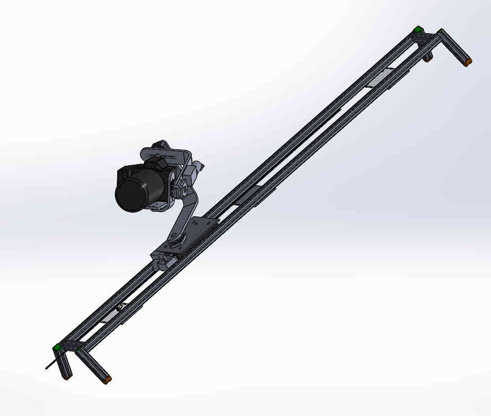
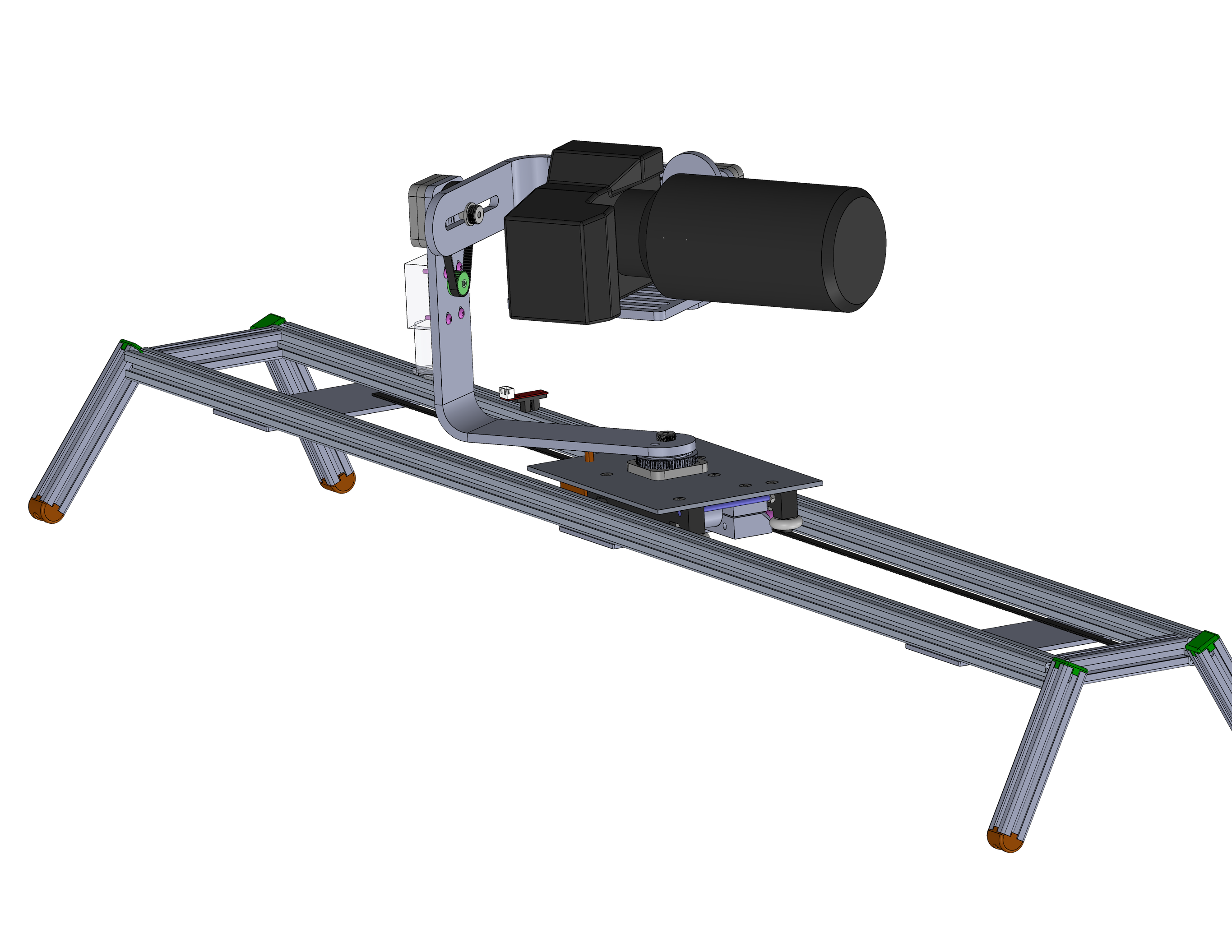
Preliminary CAD can be seen below of the design. The linear rail portion of the device is achieved
by Nylon coated bearings rolling in the groove of aluminum extrusions. The carriage contains a
geared DC motor with a GT2 timing belt pulley. A length of timing belt runs the full length of the
rail that engages the motor. Flags at each end of the rail interrupt an optical endstop next to the
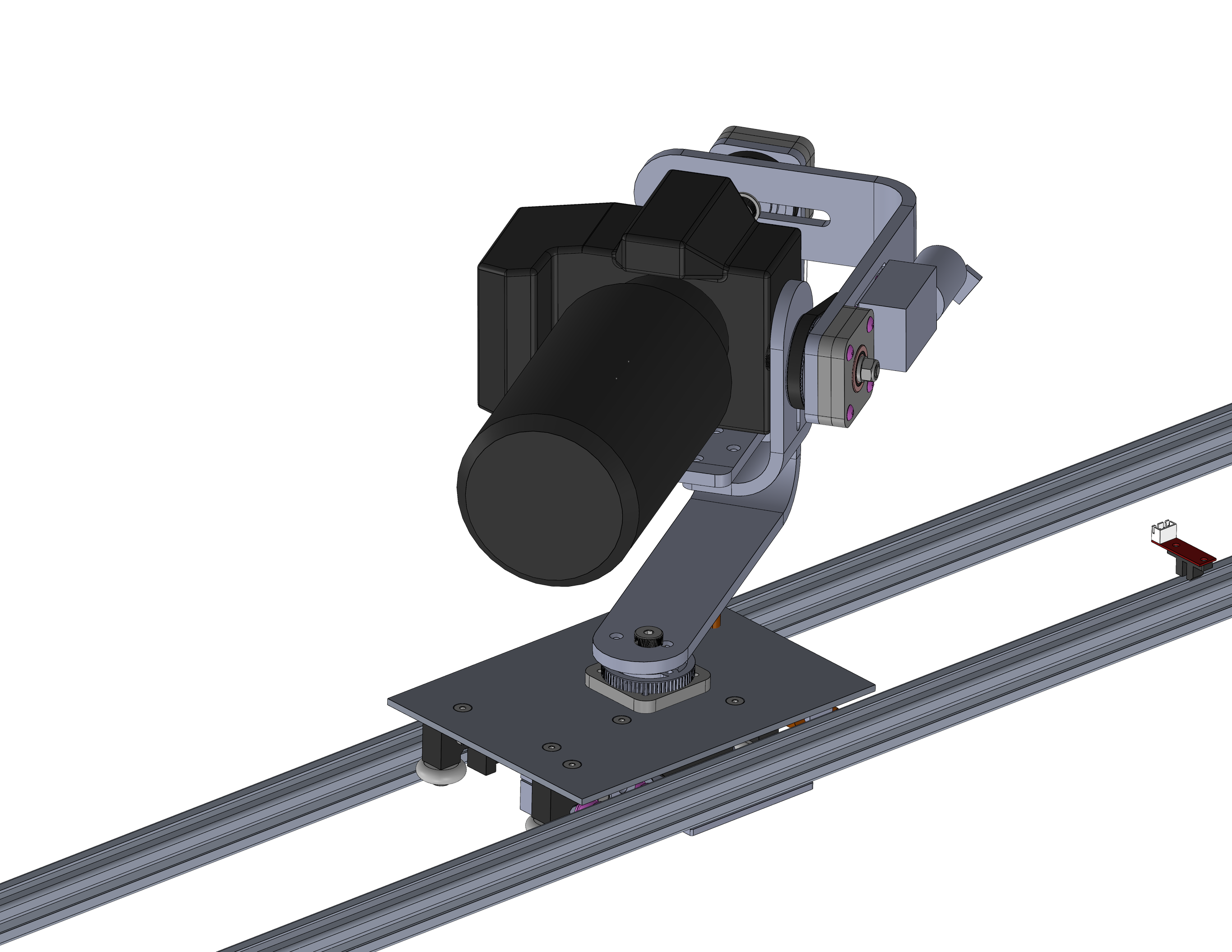
motor. This allows the device to be homed after power up. The carriage also contains a 3 axis
gimbal. Each axis contains its own geared motor to drive that axis. The design allows all
electronics to be all housed on the carriage, without any wires needing to be run off the device.
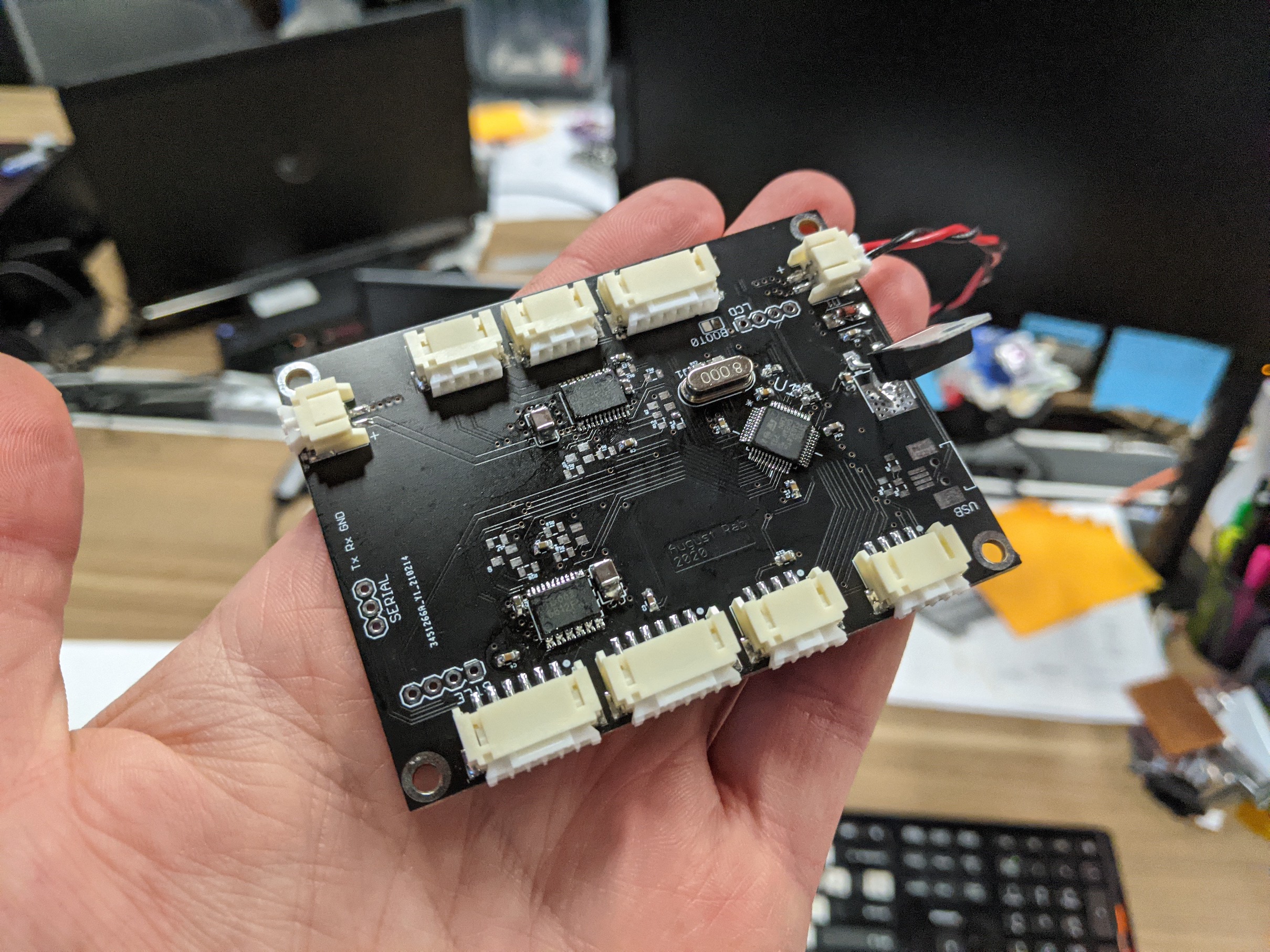
The electronics consist of a custom PCB that contains a low power microcontroller, four low level
motor drivers, a small OLED display, and a bluetooth adapter. The PCB has connectors for serial,
USB, and wireless communication. Additionally, a power control circuit was added to allow the entire
system to be run from a three cell lithium battery. A photo of an early prototype PCB can be seen
below.
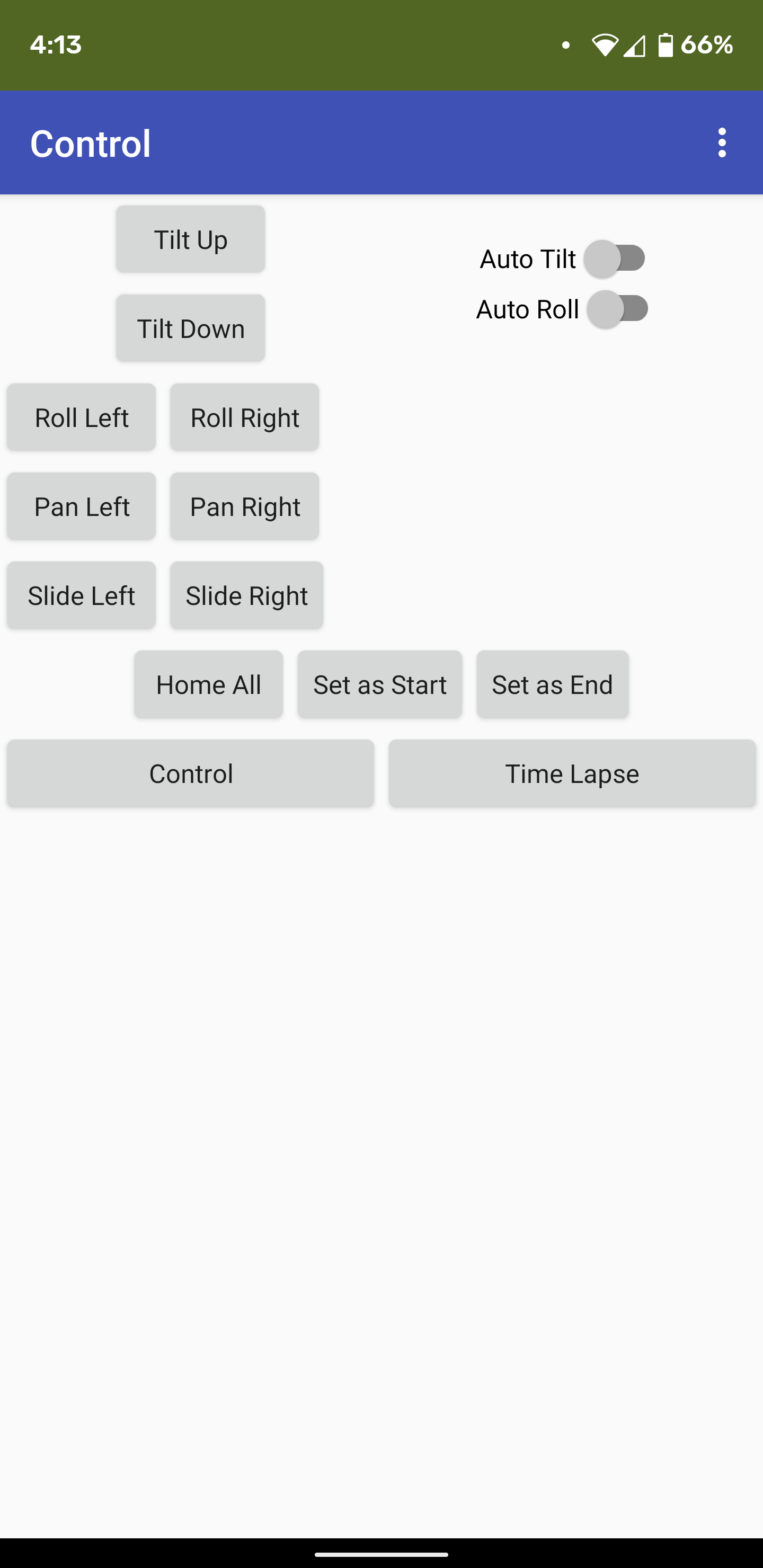
Since the device needs to be very still during use, the bluetooth connection was included instead of
physical buttons or controls. An android app communicates to the microcontroller via the bluetooth
link to manually control the camera, gimbal, linear rail, as well as program in timelapse settings
and see status information
The short video below shows a few clips I recorded while testing the mechanical function of the rotation and linear axes.
The microcontroller on board handles the positioning calculations, interpolating between the start
and end quaternions, converting them to euler angles (the positions for each of the drive motors).
This produces an effect known as slerp (spherical linear interpolation). Slerp is a movement about
the surface of a sphere in a single plane that includes both the movement arc, as well as the sphere
center.
Unfortunately the great chip shortage of 2021 is delaying progress on this project. Early designs
used a fairly small STM32F103 that was cheap and ubiquitous. However I am in progress of upgrading
the design to use a larger, more powerful processor. This will allow better, smoother movement and
faster response, as well as a number of other fancy software features such as jerk limiting,
multiple path chaining, and acceleration and jerk limiting, and possibly even object tracking or
other dynamically generated movement.