Many Almost all of the projects I work on involve electronics. Whether it’s complex digital circuitry,
or just a simple LED or motor, I have to have some way of powering the device. Too many times I found
myself rummaging through a bin of power supplies, and using alligator clips to wire it to my circuit.
This is often very precarious, with exposed metal clips and wires all over the place. It also is often
frustrating when I can’t find a suitable power supply for my project.
At Georgia Tech’s Invention Studio, I have access to a range of electronic tools. Included is a very
nice 3 amp, 30 volt dual rail power supply. This is perfect for all of my needs. However when I’m not
at school (over summer or winter break and of course after I graduate) I don’t have any nice power
supply solutions. These types of power supplies are not too expensive, however they’re not cheap either.
They are the type of thing that can cost anywhere from $100 for a basic supply to a few thousand dollars
for a dual rail supply with all sorts of extra features. For my needs even a basic power supply works
fine. I wouldn’t want to simply buy one, that would be too easy. So I started to design my own of course.
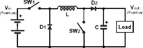
After many, many hours of research and thinking, I finally settled on a non-inverting buck-boost topology.
A buck converter is a type of converter than reduces voltage while increasing available current; a boost
converter increases voltage while decreasing available current. A buck-boost converter uses both aspects
to achieve a voltage that is either higher or lower than the input. This type of supply is a slightly
different topology than most supplies. However it allows for some interesting features that only more
expensive power supplies usually have such as floating outputs. Below is the basic non inverting buck-
boost schematic. It is basically two converters that share a common inductor.
 Rather than designing a power supply that plugs directly into a wall, I wanted to design my power supply
to run at 12 volts from a computer power supply. This has the advantage of
being safer, and it also allows the supply to plug into a 12 volt cigarette lighter socket if the need
were ever to arise (for example charging RC batteries when away from any 120 V outlets). After many more
weeks and much more research, I developed a first draft schematic.
Rather than designing a power supply that plugs directly into a wall, I wanted to design my power supply
to run at 12 volts from a computer power supply. This has the advantage of
being safer, and it also allows the supply to plug into a 12 volt cigarette lighter socket if the need
were ever to arise (for example charging RC batteries when away from any 120 V outlets). After many more
weeks and much more research, I developed a first draft schematic.
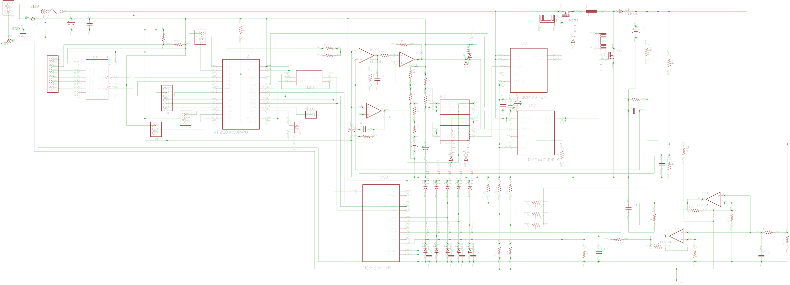 Obviously this is much more complex than the basic model above. This schematic includes feedback networks,
analog to digital converters, operational amplifiers, plugs and sockets for buttons and an LCD screen,
MOSFETs, MOSFET driver, and, of course, my favorite micro controller (Atmel’s ATmega328p) to run
everything. Being digitally controlled not only gives the ability to have a digital LCD, but it opens
a world of possibilities such as serial communication, programmed voltage or current profiles, low
frequency signal generation, instantaneous power readout, total energy output, rechargeable battery
statistics, and so much more.
Obviously this is much more complex than the basic model above. This schematic includes feedback networks,
analog to digital converters, operational amplifiers, plugs and sockets for buttons and an LCD screen,
MOSFETs, MOSFET driver, and, of course, my favorite micro controller (Atmel’s ATmega328p) to run
everything. Being digitally controlled not only gives the ability to have a digital LCD, but it opens
a world of possibilities such as serial communication, programmed voltage or current profiles, low
frequency signal generation, instantaneous power readout, total energy output, rechargeable battery
statistics, and so much more.
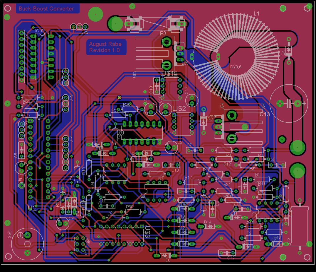 Above you can see the PCB layout that I generated from the schematic. The red layer is the top of the
board, the blue layer is the bottom, the green dots are component mounting pads, and the white outlines
show where each component goes.
Above you can see the PCB layout that I generated from the schematic. The red layer is the top of the
board, the blue layer is the bottom, the green dots are component mounting pads, and the white outlines
show where each component goes.
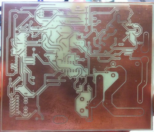
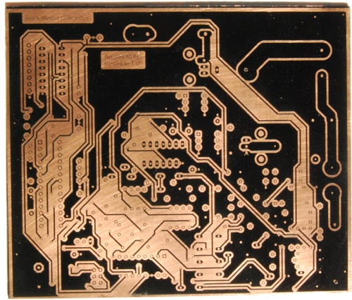 Above you can see the copper board before etching. The black coating is generic spray paint. To cleanly
transfer the PCB pattern onto the copper board, the copper was first cleaned and coated with spray paint,
and then put into the laser cutter at Georgia Tech’s Invention Studio. The image of the top and bottom of
the PCB were then used to engrave away the spray paint everywhere the copper needed to be removed. The
laser cutter can’t cut the copper itself, so the painted board was then etched normally in a PCB etching
solution. The first try didn’t come out too cleanly as can be seen below. A few of the traces in the center
etched away where they weren’t supposed to. A better quality spray paint solved this.
The only thing left to do is drill all of the tiny holes, and solder in the components. Well that, and test, debug,
program firmware, etch a new board, wash, rinse, repeat...
Above you can see the copper board before etching. The black coating is generic spray paint. To cleanly
transfer the PCB pattern onto the copper board, the copper was first cleaned and coated with spray paint,
and then put into the laser cutter at Georgia Tech’s Invention Studio. The image of the top and bottom of
the PCB were then used to engrave away the spray paint everywhere the copper needed to be removed. The
laser cutter can’t cut the copper itself, so the painted board was then etched normally in a PCB etching
solution. The first try didn’t come out too cleanly as can be seen below. A few of the traces in the center
etched away where they weren’t supposed to. A better quality spray paint solved this.
The only thing left to do is drill all of the tiny holes, and solder in the components. Well that, and test, debug,
program firmware, etch a new board, wash, rinse, repeat...